Media
Progress
This media page is a tool that will help spectators see progress in the experimentation. Progress can be seen in a visual form or an audio form. These include sketches, videos, audios, drawings, and photos.
Methods/Materials
This image represents the first attempt at determining the materials/methods for the building process of the experiment. The drawings and text are representations of the broad ideas necessary to understand the overall building process for the wind tunnel. From this, more details can be added to each step.


Experimental Process
This is the first attempt and rough sketch of how the experimental process will appear. The sketch is a very important element because it provides a visual to help guide the experimenter see which part of the experiment is taking place.
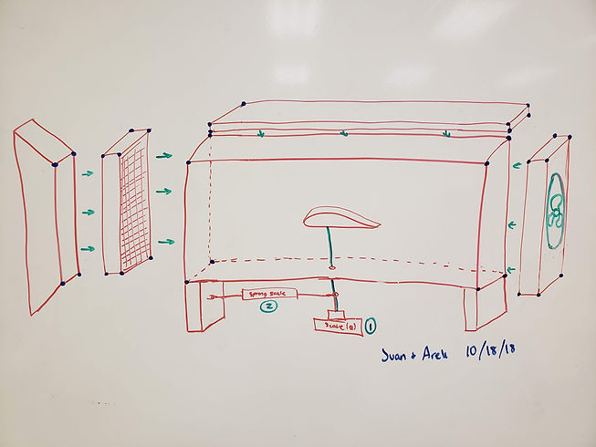
Experimental Process and Data Collection
This carefully designed sketch is the final version of the experimental process. The image shows how the wind tunnel will be assembled and how the data will be collected, represented by the numbers.
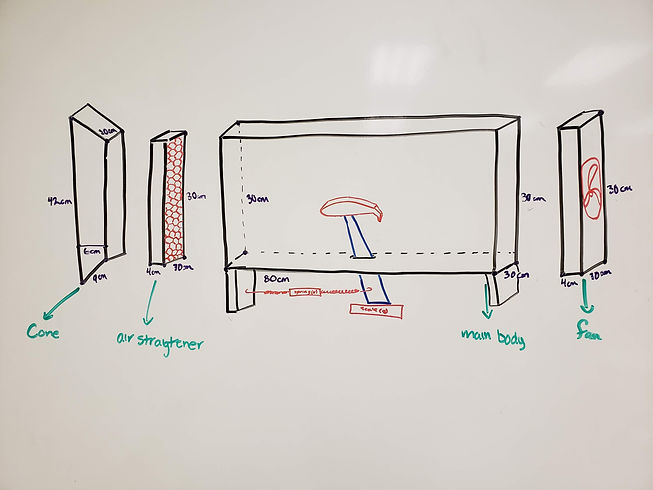
Wind Tunnel Design 1
This image shows the diagram of what the wind tunnel will look like with dimensions. The parts of the wind tunnel are the cone, air straightener, main body, and fan.
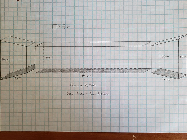
Wind tunnel Design 2
After reviewing the physics of fluids, we have made the body of the wind tunnel shorter so the air can travel faster.


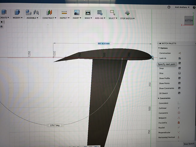
Airfoil Model
This is the constant airfoil being modeling in Fusion 360. This is one of five airfoils that will be modeled and printed.
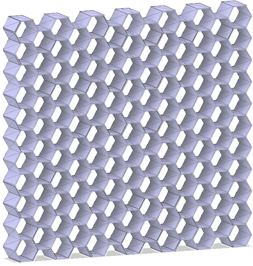
Honeycomb Air straightener
This is a model of the honeycomb air straighter, and it was modeled in Fusion 360. The air straightener goes at the front of the wind tunnel and it makes sure that there is laminar air flow in the wind tunnel.

CNC Machine Controller
The box-like machine is the CNC machine controller. It controllers the router in the x, y, and z position. It tells the CNC how to move and it can stop the machine if something would to go wrong.
Straw Air Straightener
The honeycomb air straightener was ended because it took a lot of material and time to print. We switched to the staw air straightener because it would save time and materials; however, it is currently holding us back from continuing and experimenting.


Scrap Material
These are four scrap pieces from the cutting process. They are glued together with an adhesive. The purpose of this was to test if the adhesive would work with the acrylic, and it does work.
Wind Tunnel Design 3
This is a sketch of the final wind tunnel design. Since the last version, it was discovered that both the front and back tapers were too short. This was an issue because the fan would not fit inside of the back taper. To fix this problem, the tapers' length was increased by 10 cm.
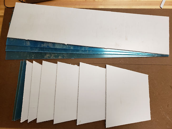
Wind Tunnel Components
These are the pieces of acrylic that were cut by the CNC machine. These will be used to construct the frame of the wind tunnel.
End of the Wind Tunnel
This is the very end of the wind tunnel. The fan is surrounded by four pieces of acrylic. This is a dry fit of the back of the wind tunnel, and the purpose of this was to see if the measurements of the shapes were correct.

Airfoil Model 2
This is an updated version of the constant airfoil. The last airfoil design had too many rough corners on its surface and was not the right shape. This is a model of a Clark Y airfoil, which has an almost flat underside. Also, since this photo was taken, the base support has been removed because it would not 3D print with it attached. Instead, scrap material was used to create one base for all five airfoils.
Airfoil Modeling
This is an image of the constant airfoil being modeled in Fusion 30. After many attempts to decide on a procedure of modeling the airfoils, one was created; this shows a part of that created procedure.

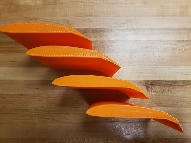
3D Printed Airfoil Models
After creating the models of all five airfoils, they were 3D printed. This image only shows the airfoils with secondary angles of 5, 10, 20, and 40 degrees.
3D Printed Airfoil Model with Support
This is an image of the 3D printed airfoil model with the acrylic base support. The support was attached to the airfoil using hot glue. The reason for this is we want to reuse the same support for all of the other airfoils, and hot glue is not permanent.


Straw Airflow Straightener 2
This is a picture of the straw airflow straightener. It resembles the honeycomb airflow straightener in that it creates a stream of laminar flow air inside of the wind tunnel, which reduces turbulent air. It was constructed out of straws and glued together using hot glue.
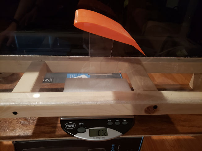
Constant Airfoil Lift Trial (before)
This image shows the initial mass, 103.2 grams, of the constant airfoil-strut system for the first lift trial (before). The airfoil was placed inside of the wind tunnel so that the air would flow (in this image) from the left to right. The mass was converted into kilograms and recorded in Data Table 1.
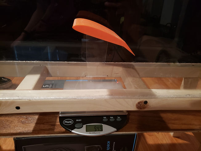
Constant Airfoil Lift Trial (After)
This picture shows the final mass, 94.9 grams, of the constant airfoil-strut system for the first lift trial (after). Shortly before the image was taken, the wind tunnel’s fan was turned on and was allowed enough time to reach its maximum velocity. The mass was recorded when it reached a constant value, converted to kilograms, and placed in Data Tabe 1.
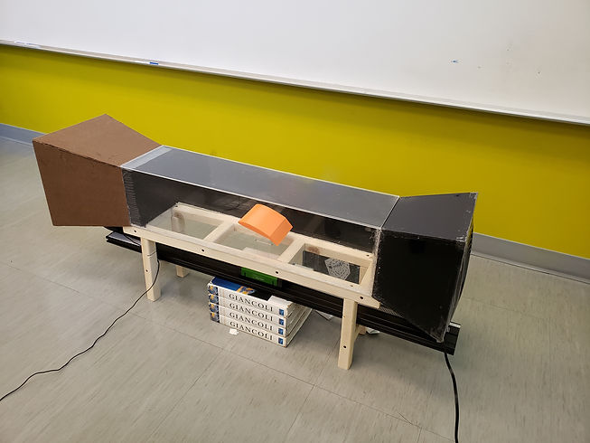
Set Up for Drag Trials
This image shows the set up for the drag trials of the aifoils. Below the wind tunnel lies a Vernier dynamic track and on that a Vernier cart. This allows the cart to move with very little friction. When the fan is turned on, the cart begins to move to the right, but before it touches the edge of the strut opening, a string tugs on it and the force is recorded by a force sensor.

Constant Airfoil Drag Trials
This image shows the set up for the drag trials of the airfoils. Below the wind tunnel lies a Vernier dynamic track and on that a Vernier cart. This allows the cart to move with very little friction. When the fan is turned on, the cart begins to move to the right, but before it touches the edge of the strut opening, a string tugs on it and the force is recorded by a force sensor.